aim is to use an OpenWRT router to support a Bullet or an M900

On this OpenWRT router I went to its "switch" tab. And then I created an independent VLAN (VLAN 2) that the main LAN (VLAN 0) won't "see" Thus I can have say the 10.x.x.x network traffic and 192.168.1.x traffic never see each other. Okay, what did this get me as far as AREDN goes? I am thinking I could reselect these ports and VLANs to do the same thing we have Netgear smart switches doing. As most of us have WRT54Gs laying around... One port to feed the Bullet, another becomes the WAN for the Bullet, another the DtD port and others becomes the Bullet's LANs.
One thing to remember! Be sure you have the CPU "port" accessible to the LAN, else you won't be able to reach the OpenWRT web GUI again!
You are here
OpenWRT router to act like a Netgear smart switch on AREDN node
Fri, 03/01/2019 - 14:50
#1
OpenWRT router to act like a Netgear smart switch on AREDN node
Theme by Danetsoft and Danang Probo Sayekti inspired by Maksimer


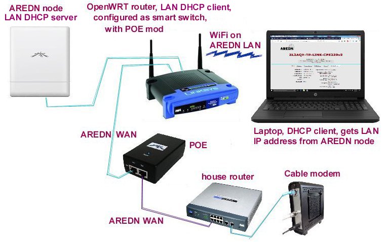
Made some progress in getting an OpenWRT router act like a Netgear smart switch to service an AREDN node with just one ethernet jack, Like a Bullet,.to split off its WAN, LANs and DtD signals. In the OpenWRT web GUI, set its LAN to be a DHCP client. The AREDN node will be the DHCP server. And go to the switch tab, and set things as below:
Of course this is meaningful only if you happen to have some OpenWRT routers (like WRT54G's) laying around....
This OpenWRT router (a WRT54G V2.2) as a Netgear smart switch has worked fine 3 months now without any issues.
I did an additional mod to it, to have it run off the Ubiquiti POE power supply, and pass the POE to also power the Ubiquiti M900 node. I connected jumper wires between the ethernet jacks that are for the node, and the WAN connection, the blue and brown twisted pairs. Remove 75 ohm resistors RD13 and RD1, as these would introduce an unneeded extra load on the POE. And from the brown jumper wire I connected via a 5V 5W Zener diode to the router's ground, and from the blue jumper (the positive supply) a regular rectifier diode to the router's power rail (the WRT54G V2,2 uses a diode from the power jack to the internal power rail (protection from backwards wall warts)). As the router's internal DC-DC converters are rated a max of 24VDC, and the Ubiquiti POE brick produces 24VDC, I used these diodes to knock this 24V to 18V inside the router. I didn't want to run the converter chips on the edge... I attached some heat sinking to the Zener diode, on its leads I soldered some pieces of copper clad circuit board, runs cool. The Ubiquiti POE brick has no problem with the extra load. And one less 120V brick in the shack.
And yet another mod is to make the router be able to pass the Ubiquiti POE brick reset signal to the Ubiquiti node. Ubiquiti uses a push button to introduce a small current onto the green and orange ethernet twisted pairs that a circuit in the node will use to trigger a reset. So one needs to connect the ethernet transformers' external windings center taps together (from the WAN port to the node port). You need to remove 75 ohm resistors RD14 and RD2. And connect a wire to one side of these surface mount pads (the pads that connect to the transformer centertaps). On the back of the board, connect a 0.1uF cap from the transformer TU3 centertap you just connected the jumper to, to ground.
Possibly a significant feature of this OpenWRT router use: it can provide a part 15 wifi connection to the Ubiquiti's LAN. The Ubiquiti node's LAN would be the DHCP server. Configure the wireless device to be a DHCP client, and it will get an IP address from the Ubiquiti node's LAN.

73, Dean, KC2MVB